In our previous article on Ball Grid Arrays (BGAs), we explored how to design circuit boards and how to route the signals coming out of a BGA package. But designing a board is one thing – soldering those chips onto the board is quite another. If you’ve got some experience with SMD soldering, you’ll find that any SOIC, TQFP or even QFN package can be soldered with a fine-tipped iron and a bit of practice. Not so for BGAs: we’ll need to bring out some specialized tools to solder them correctly. Today, we’ll explore how to get those chips on our board, and how to take them off again, without spending a fortune on equipment.
Tools of the Trade
For large-scale production, whether for BGA-based designs or any other kind of SMD work, reflow ovens are the tool of choice. While you can buy reflow ovens small enough to place in your workshop (or even build them yourself), they will always take up quite a bit of space. Reflow ovens are great for small-scale series production, but not so much for repairs or rework.
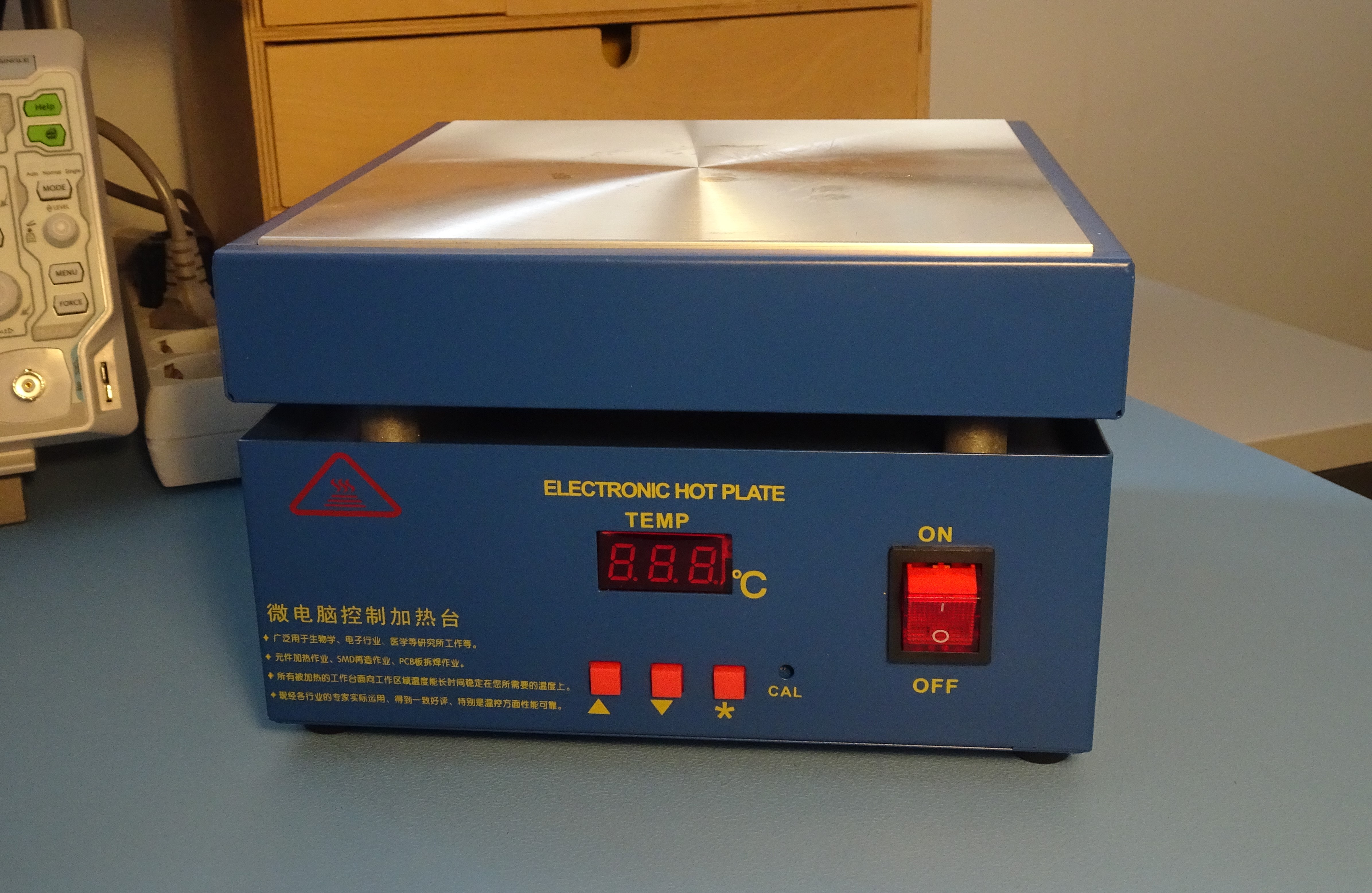
A smaller, cheaper and arguably more versatile tool is a hot plate. Although you can convert cooking appliances into soldering hot plates, it’s more convenient to buy one specifically made for the purpose with an adjustable temperature controller. Also known as “pre-heaters”, these can be had for less than $100 from the usual online channels. They’re pretty easy to use, too: simply place your board on top, set the desired temperature and wait for the solder to work its magic.
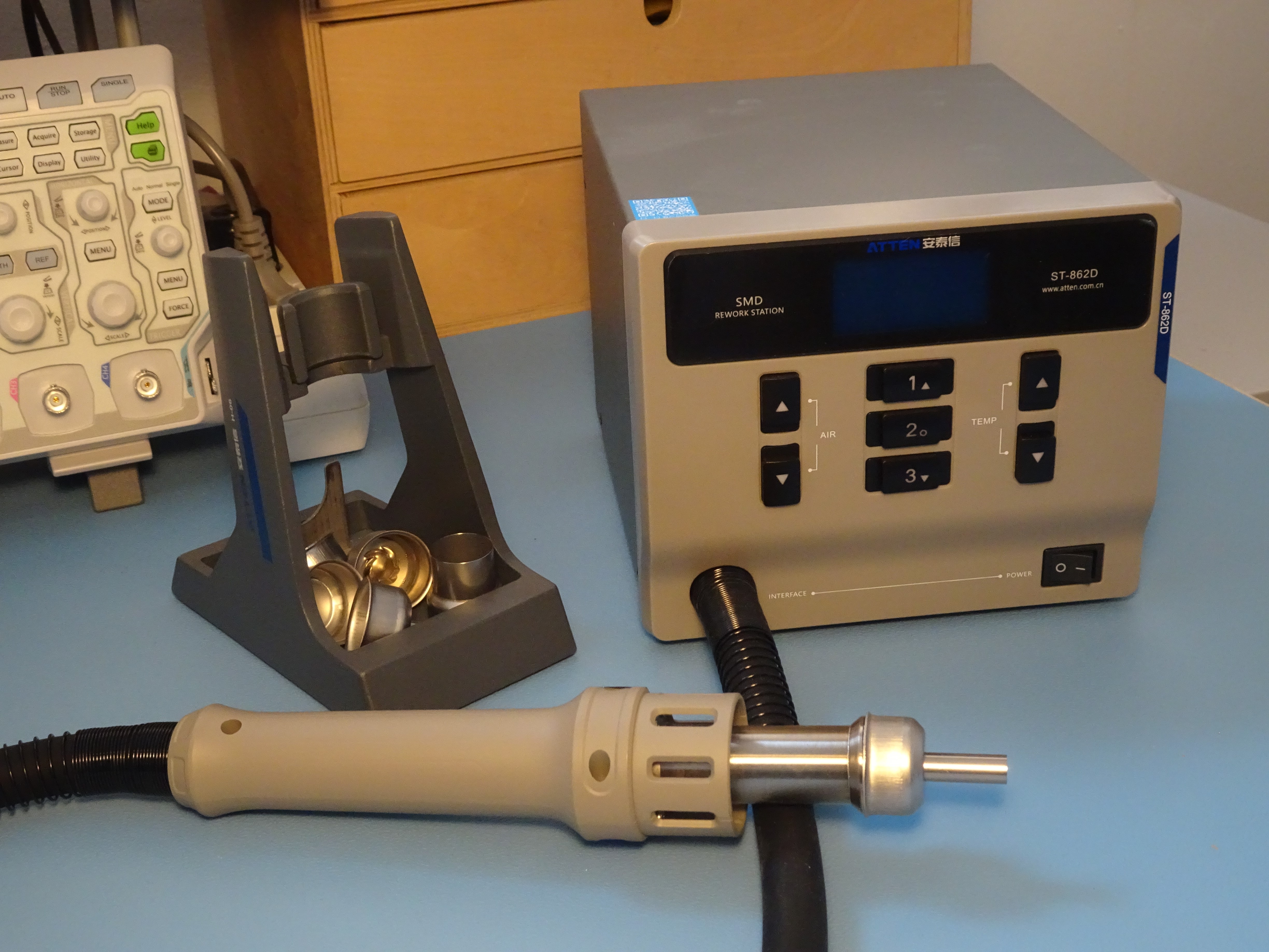
A drawback of hot plates is the fact that they heat up the entire board at once, making them less than ideal if you want to solder or desolder a single component. For that, a hot-air soldering station is the tool to use. Professional hot-air stations can run into thousands of dollars, but you can buy lower-range models, with adjustable temperature and airflow, for between $100 and $300.
Hot plates and hot-air soldering stations also work together very well: the hot plate can be used to pre-heat the entire board to about 150 °C, with the hot air gun used on just the part to be soldered. This reduces thermal stress on the board compared to heating up just one spot all the way from room temperature.
If you’re starting from scratch and are wondering what tool to buy for your first BGA project, here’s our advice: as a bare minimum, buy a hot plate; if you can spend a little more, get a hot-air soldering station; and if you want the best possible toolset, buy both.
Soldering – Get that stencil ready
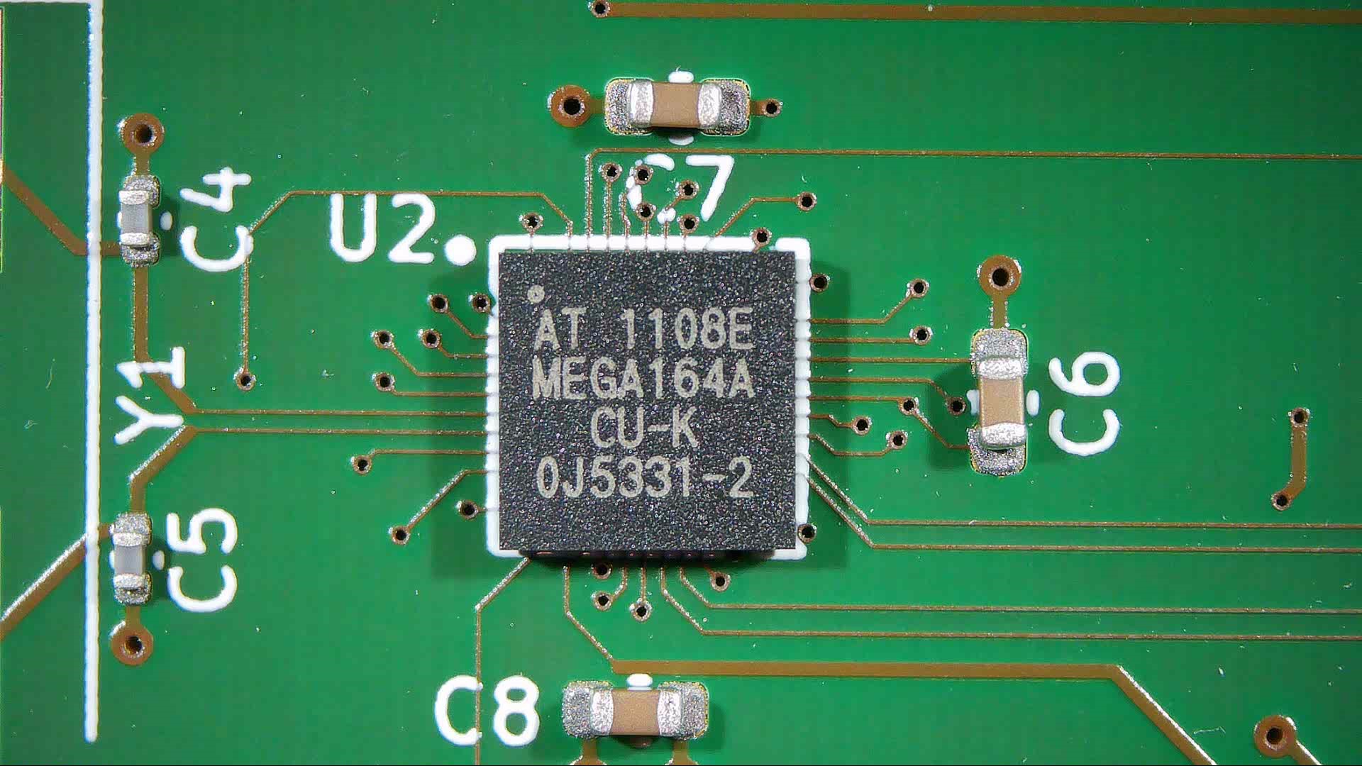
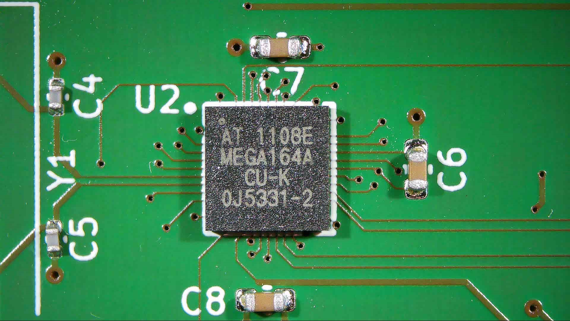
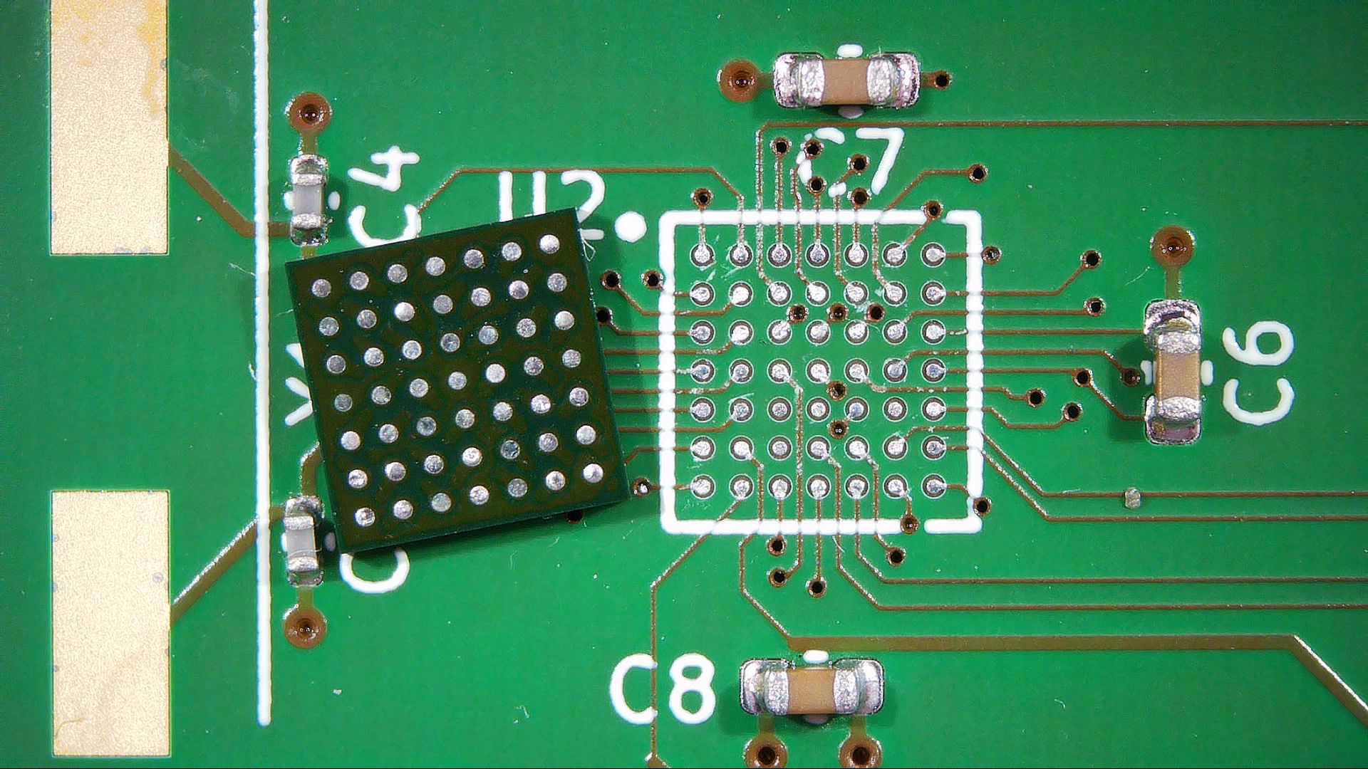
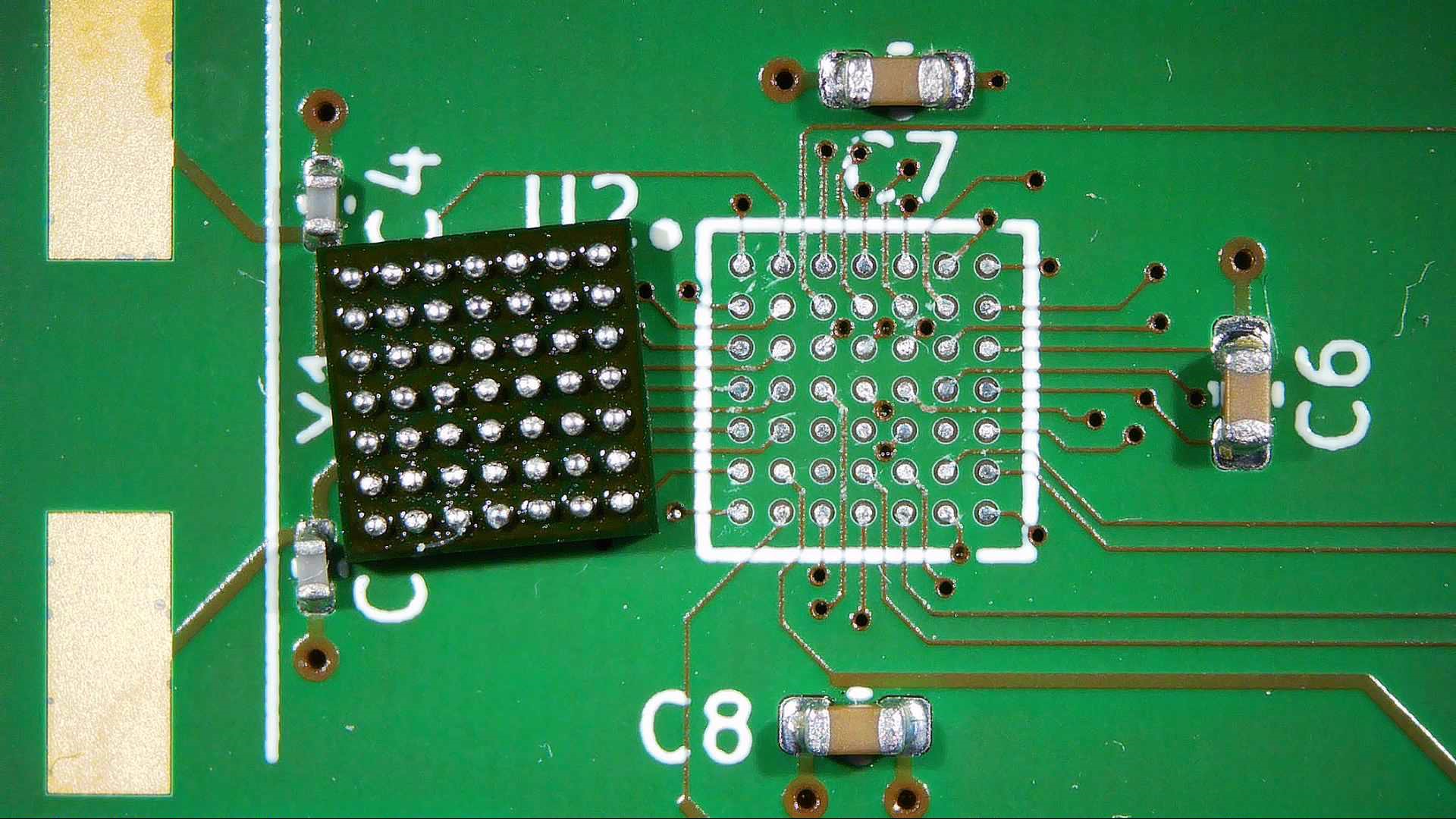
No matter whether you use an oven, a hot plate, a hot-air station or any combination of those tools, the basic steps for soldering BGA chips are the same. Let’s start from the bare footprint for the 49-ball ATmega164 that we designed last time:
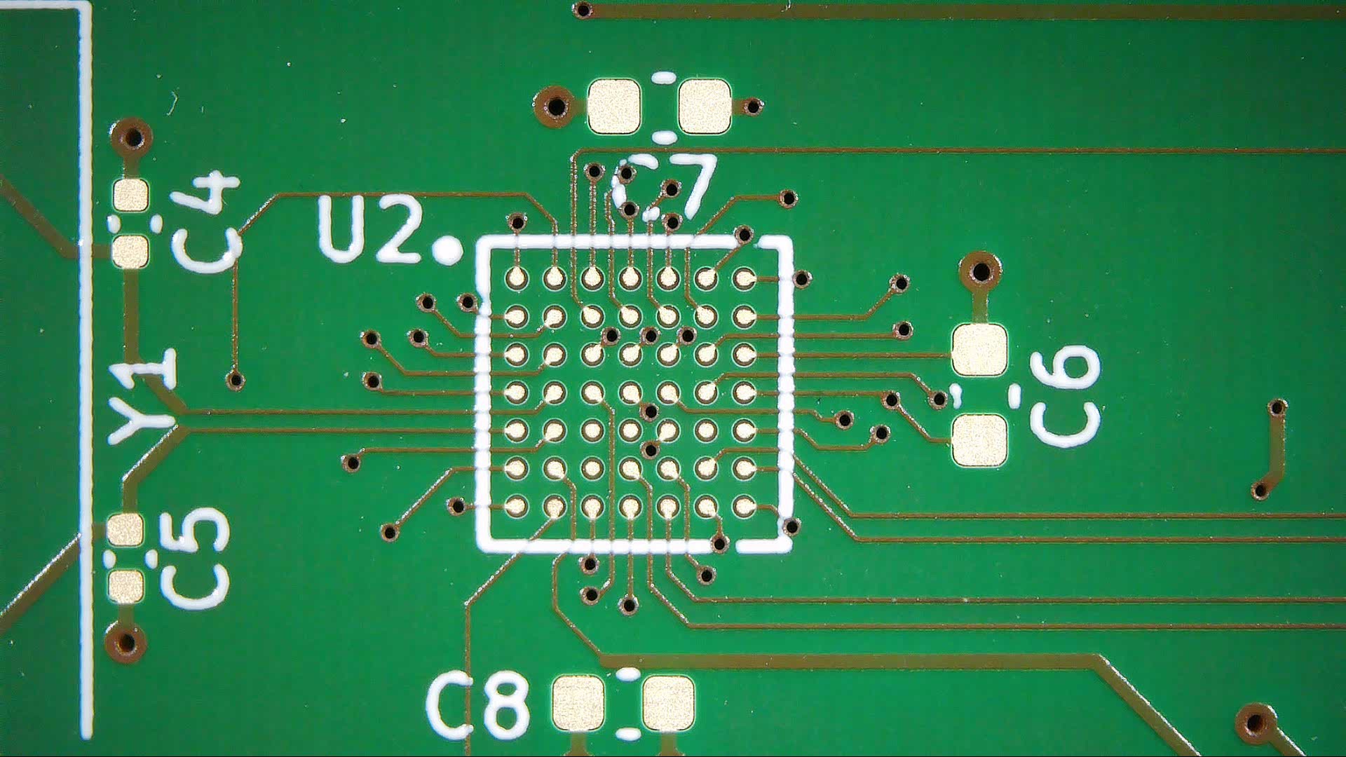
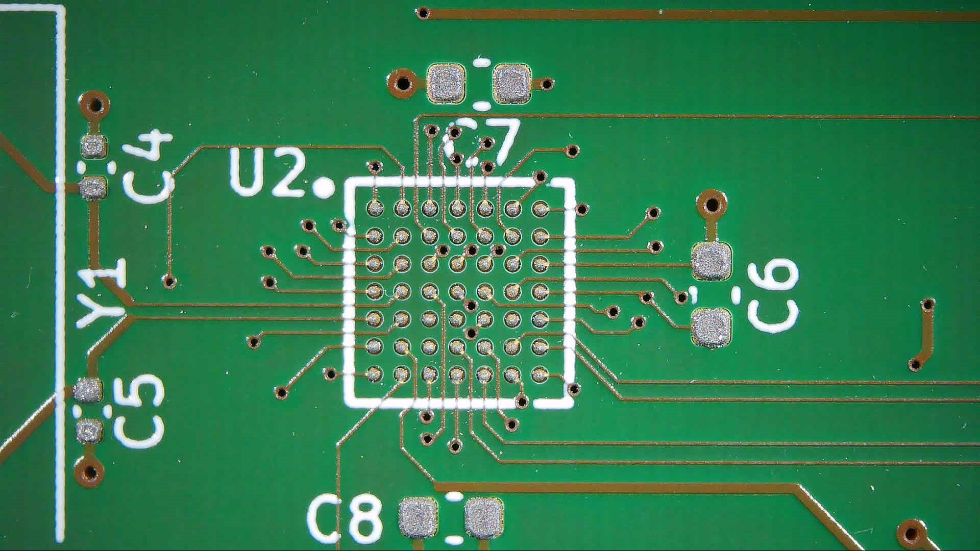
The first step is to deposit solder paste using an SMD stencil. Most PCB manufacturers nowadays offer the option to order a stencil along with your boards, and this is convenient if you use solder paste for any SMD components, not just for BGA parts. Align the stencil with your board (a jig comes in handy here), then spread a bit of solder paste across the required area using a squeegee. You should end up with a nice, even layer of paste across all pads.
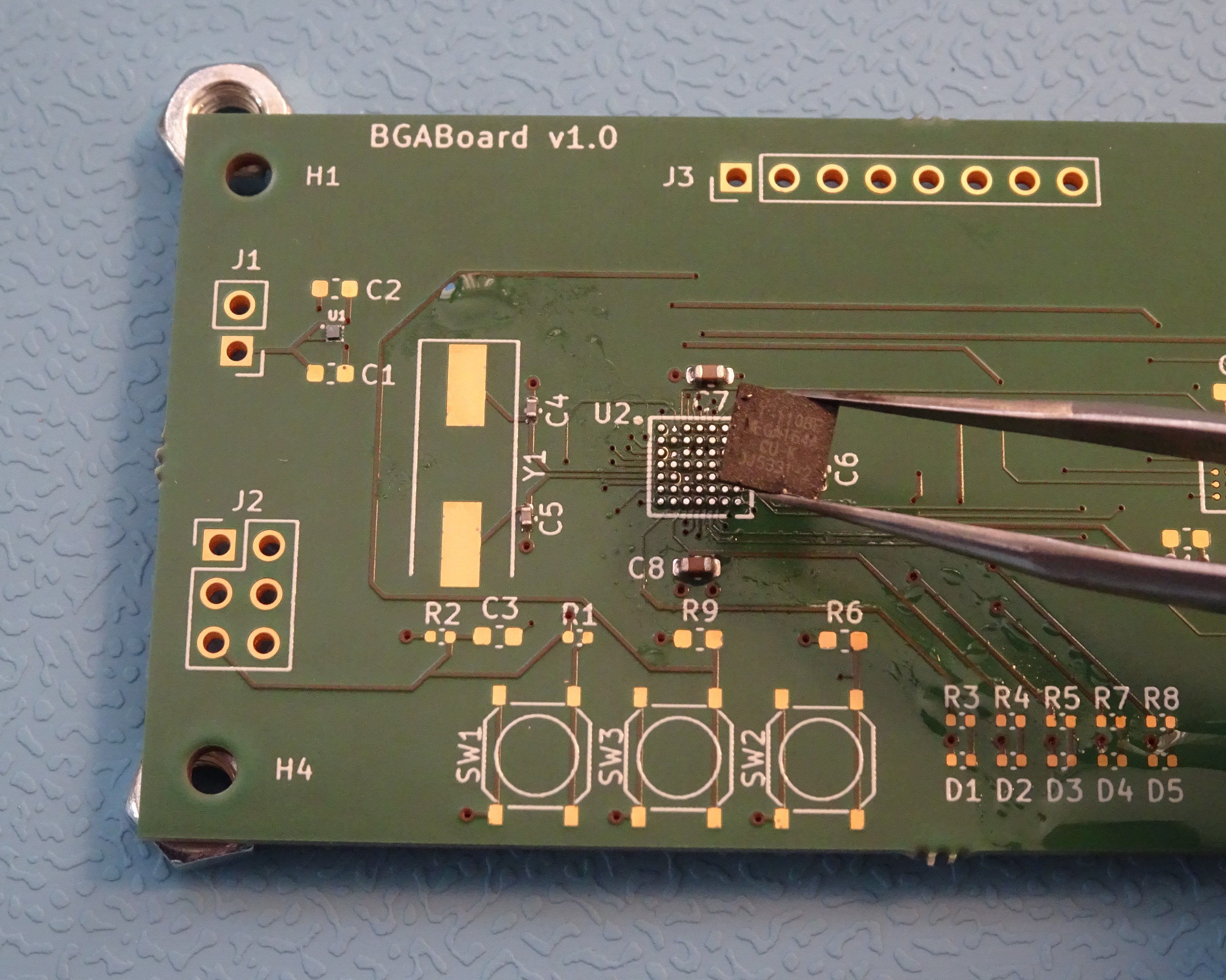
Next, we’ll place the components. You can use tweezers or a vacuum pickup tool, or even a complete pick-and-place machine if you’ve got one. Note that for the BGA chip you can’t see the pads when placing the component, so having the package outline on the silkscreen helps a lot with getting a proper alignment.
Finally, we’ll heat the board to let the solder reflow. If you’re using an oven, simply set it to the reflow profile recommended in the chip manufacturer’s datasheet. When using a hot plate, set it to the peak temperature needed: typically about 245 °C for lead-free solder. You might want to set it a few degrees higher to account for any temperature gradient between the bottom and top of the board.
As the board heats up, the BGA chip will move a little bit as surface tension aligns the chip with its footprint, but typically it’s hard to see whether the solder has properly melted everywhere. It’s convenient to place a few resistors or capacitors on the board even if you were planning to reflow only the chip, because you can easily tell from those components whether the solder has reflowed properly.
If you’re using a hot-air station, you’ll need to experiment a bit with its settings to find what works best. Especially the “flow” setting can vary quite a bit between models, so you’ll have to figure out how much airflow can be used without blowing the components all over the place. Once you’ve found the proper setting, apply the heat evenly across the chip and its immediate surroundings. When the solder balls melt, you should see the chip wiggle its way onto its footprint.
The stencil-and-paste method method is the preferred way of soldering BGAs, and is typically the method recommended in manufacturers’ datasheets. But it’s still possible to solder a chip without a stencil – sometimes you don’t even have a choice, such as when you’re replacing a chip on an existing board.
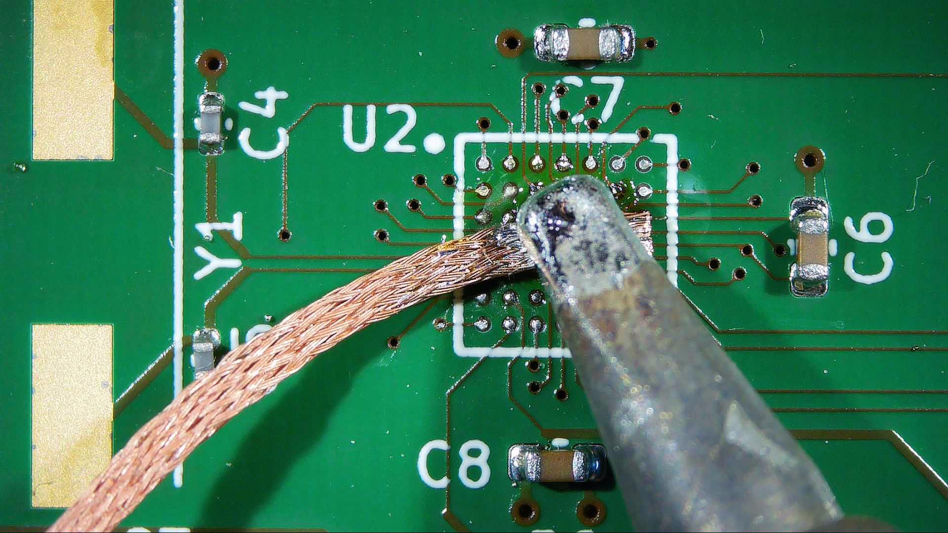
While it is possible to directly solder a BGA chip to a set of bare copper PCB pads, you’ll get better results if you apply solder to the pads first: this will ensure a solder-to-solder connection between the chip and the board, easing heat transfer. You can simply drag a blob of solder across the pads, then remove it again using desoldering braid, so that all pads are nice and flat afterwards. Make sure not to set your iron too hot, and to always dab, not drag the braid across the pads. It’s very easy to pull pads off the board if you push a hot iron down too hard.
When you’re done with the desoldering braid, clean the area using isopropyl alcohol or flux remover, then apply a thin layer of fresh flux. It’s important not to use too much, because you don’t want it to bubble and dislodge the solder balls as you turn up the heat. Other than that, you can simply reflow the board as described before.
Rework – Getting the chip off again
Even if you’ve managed to solder your chip correctly the first time, you might need to remove it again at some later point. Although you can also do this with just a hot plate, a hot air station is really the best tool for this job. If you’re working with a large board that can sink a lot of heat, preheating the whole thing makes your life much easier – without a pre-heater you’ll spend ages trying to heat the entire board by blasting at one chip.
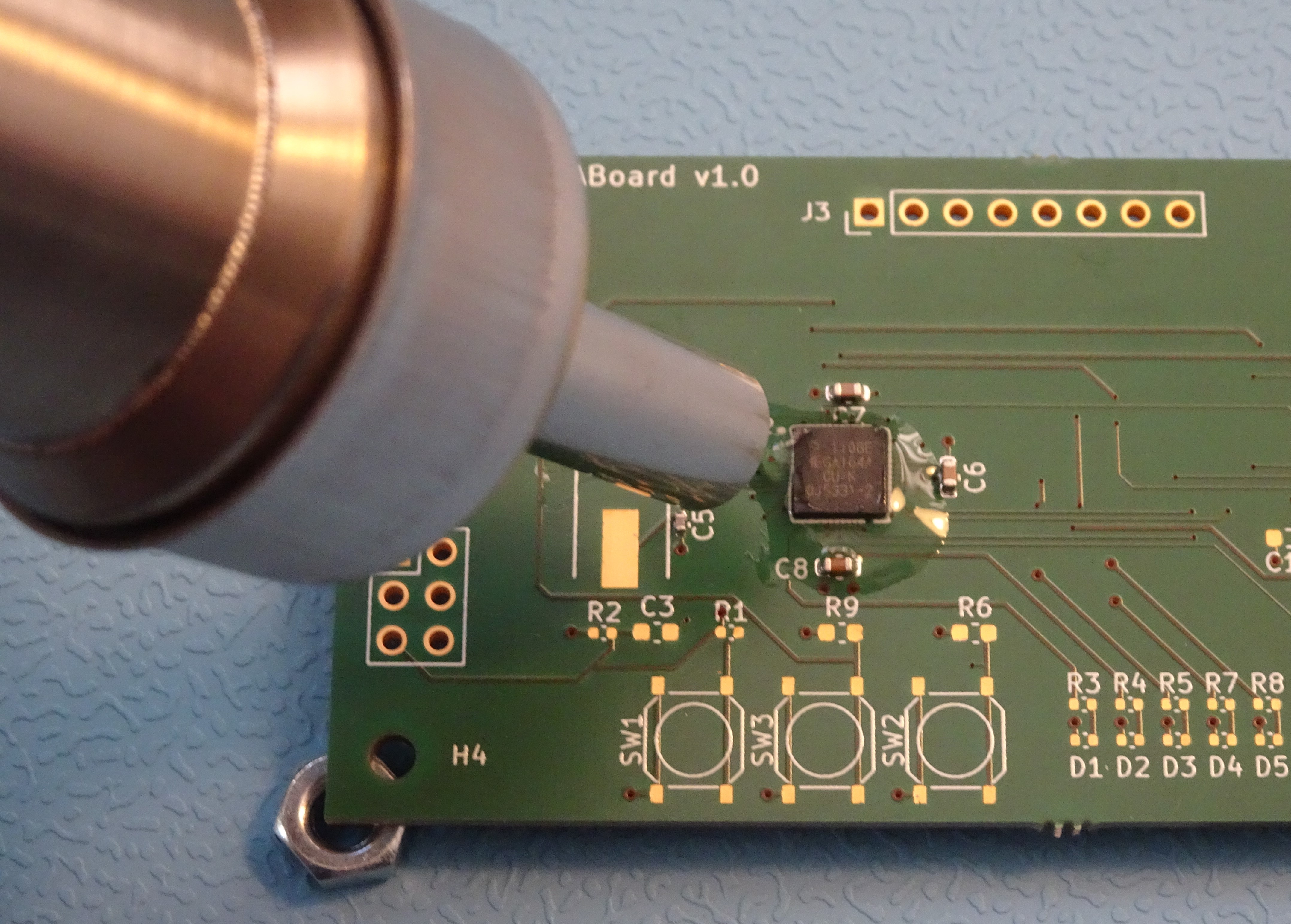
Our board is pretty small and light, so we’ll just use the hot air gun. Note how we’ve lifted the board off the table by putting small objects under the corners: this prevents the table from acting as a heat sink. Apply a generous amount of gel-type flux around the chip, then use the hot air gun to heat it up.
As you wield the nozzle, gently tug at the chip with your tweezers. You should be able to feel when the solder balls melt, at which point you should be able to lift up the chip effortlessly. Don’t use force at any time – if one or two balls haven’t melted yet, you might rip their pads off the board.
Once the chip is off, use desoldering braid and your iron to clean any remaining solder off the pads, then clean the area using flux remover. If your purpose was to place a fresh chip on the board, simply apply a fresh layer of flux and solder the new chip in place.
Things become more interesting if we want to re-use the chip as well: in that case, we’ll need to look at reballing.
Reballing – Ready for the next round
A desoldered BGA can be equipped with a fresh set of solder balls in a process known as reballing. For that, we’ll need a special tool called a reballing jig. This consists of a fixture to hold the chip as well a stencil that helps to position the solder balls. You can buy convenient kits that contain the jig, a set of commonly used stencils, a supply of solder balls and a few hand tools that might come in useful. A complete set like that will cost about $100.
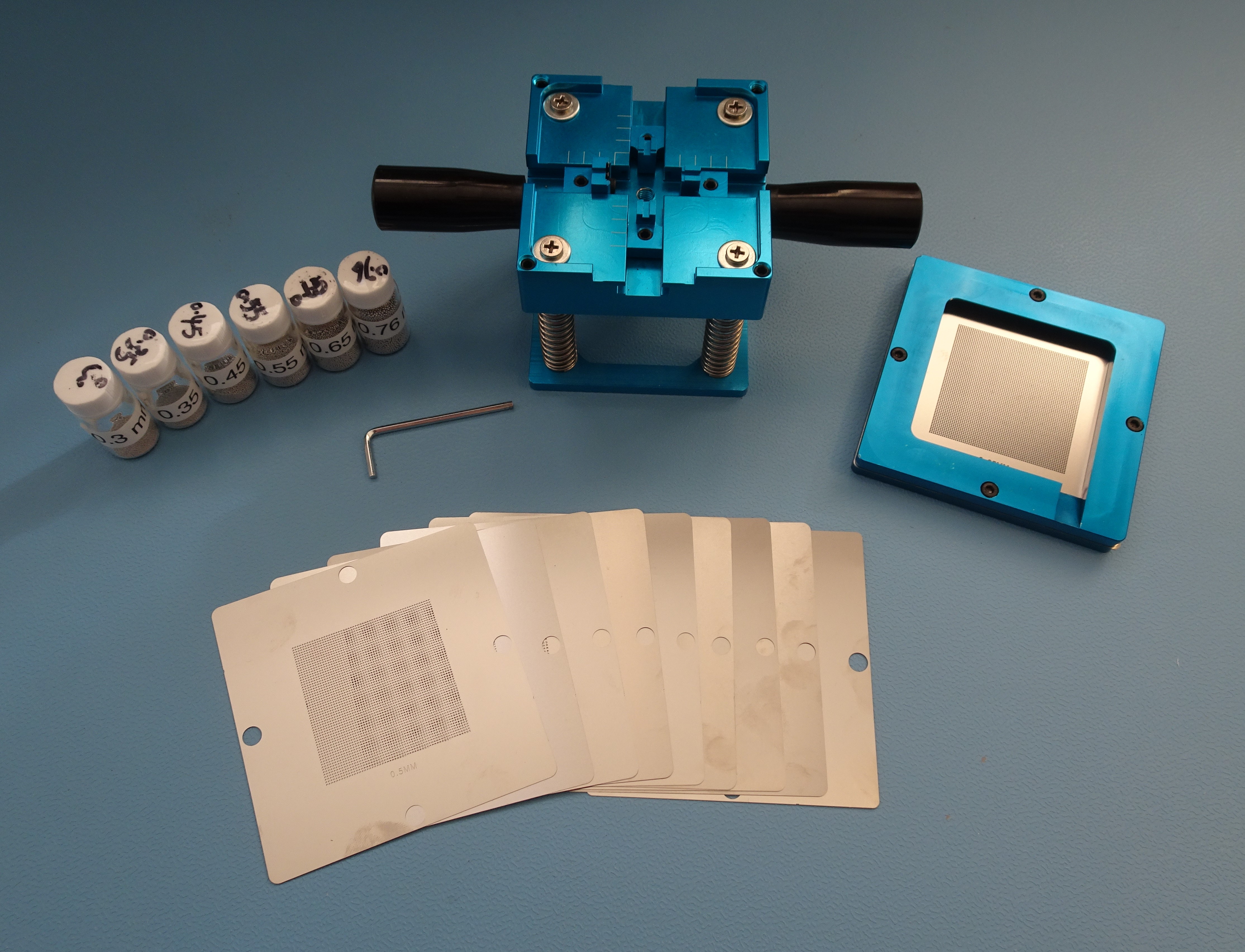
The reballing kit in our workshop came with a set of generic stencils: they differ in ball size and pitch, but have all holes placed in a regular, square grid. The idea is that you use tape to mask off the holes that you don’t need, thereby customizing the stencil to your particular chip. This works fine as long as the ball pattern on your chip isn’t too complex.
For chips with irregular ball patterns, like many memory chips, you can buy specialized stencils that exactly match those specific layouts. These are usually sold in sets that match all chips in a specific model of smartphone or tablet. Such a set is great if you’re running a repair business, but for general work a simple square set is usually sufficient.
In order to reball our chip, we’ll first clean off all remains of the old balls, just as we did on the PCB. Use desoldering braid, then clean off all remaining flux and other dirt using isopropyl alcohol or flux remover. The pads on the bottom of the chip should look flat and shiny.
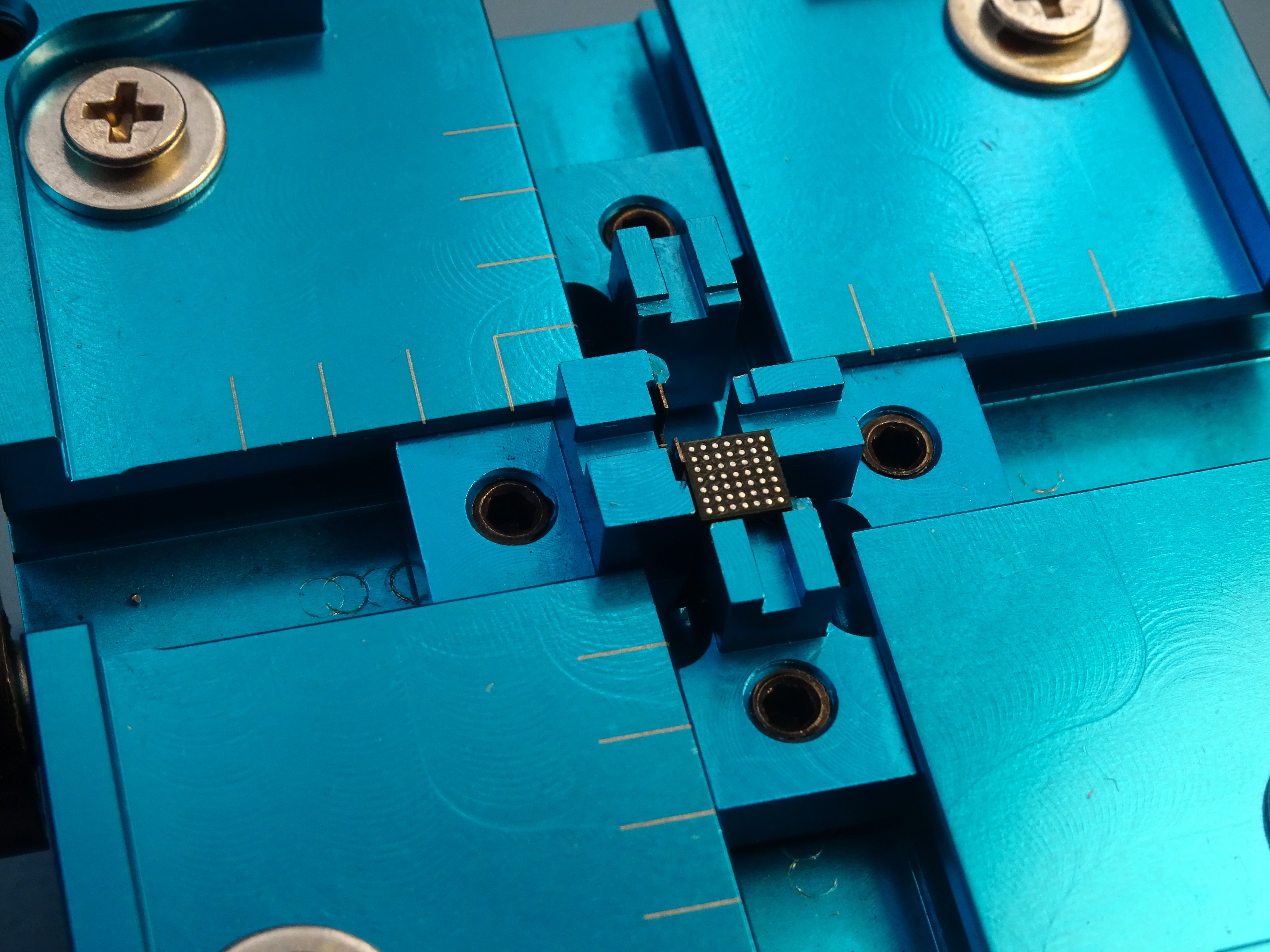
Next, we’ll mount the chip in our reballing jig. This particular model was designed for chips significantly larger than our tiny microcontroller, but we can still make it work by using only three of the four clamps. Note how the clamp on the left has a little leaf spring: we’ll position this one last, in order to put the chip under spring tension and keep it firmly in place.
Now we’ll apply a thin layer of sticky flux onto the chip’s surface, which will keep the balls in place and help them to reflow in the next step. It’s even more important here to ensure that you end up with a very thin layer, because we’ll be placing the stencil very close to the chip. If any flux ends up on the stencil, you’ll end up with solder balls stuck to the stencil rather than the chip.
Place the correct stencil inside the top part of the jig, then align it until the holes in the stencil line up exactly with the pads on the chip. Next, take some sticky tape and close off all holes that are not needed. For our little 7×7 BGA, that means taping off almost the entire stencil. Reballing kits often come with a roll of Kapton tape for this purpose, which works great, but regular Scotch tape you find in any desk drawer will do just fine, too – there’s no need for it to be heat-resistant.
Once you’re done taping, place the stencil holder back on top of the jig and pour some balls onto the stencil.
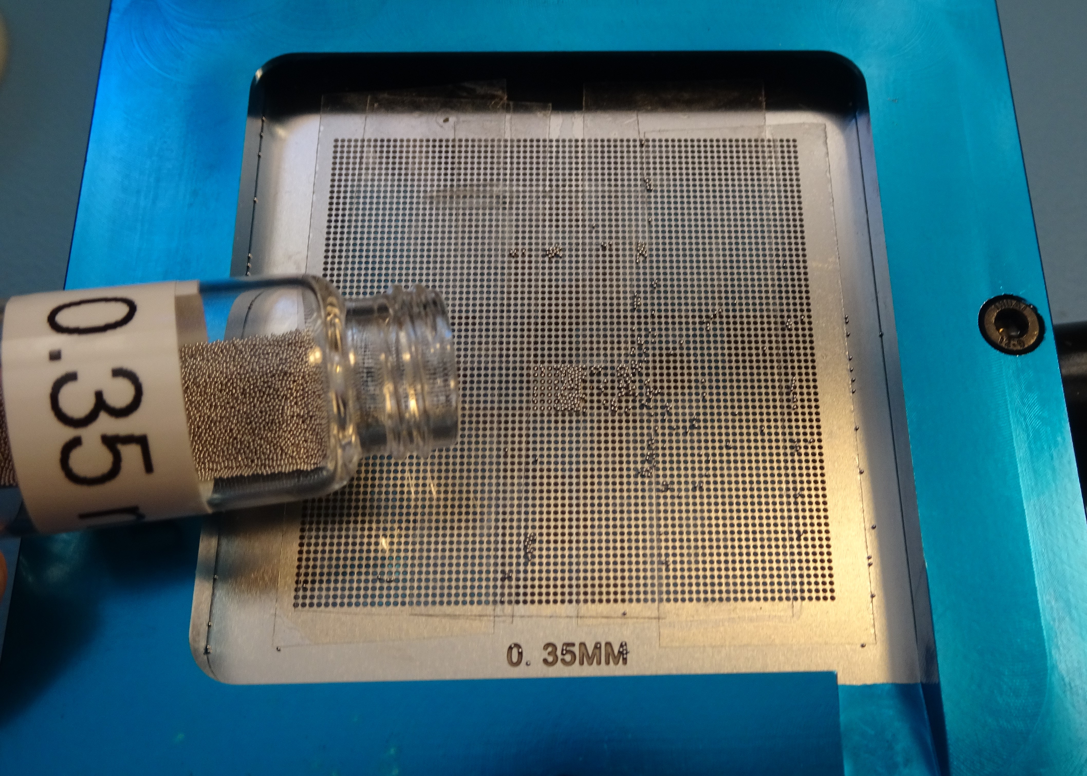
Wiggle the fixture around to ensure there’s a ball at each position on the chip. You might need to maneuver a few stubborn ones using tweezers or a fine brush. Once all slots are filled, lift up the stencil and pour any leftover balls back into the bottle using the little ramp on the bottom right of the stencil frame.
Next, we’ll need to reflow the balls onto the chip. Hot air is the easiest method here, but make sure to use a very low flow setting: solder balls weigh almost nothing and will fly away at the gentlest breeze. Alternatively, you can carefully lift up the chip with your tweezers and place it on a hot plate or in your reflow oven. In any case, once the balls reach their melting temperature you’ll see them reposition themselves and stick firmly to the pads. After the chip has cooled off, it’s ready to be mounted on a board again.
As you can see, soldering and desoldering BGAs is not that hard, as long as you’ve got the right tools. You can get even an absolute minimum toolset – a hot plate, SMD stencil and solder paste – for less than $100. This should be enough if you just need to solder the occasional BGA chip and prefer do the rest by hand.
Of course, if you were already using a stencil and solder paste to reflow your SMD boards, then throwing a BGA chip into the mix doesn’t really change the process. And if you weren’t convinced of the merits of solder paste, now might be a good time to order that stencil and try your hand at reflowing – it’s actually a very straightforward process. Now that proper SMD soldering tools are affordable even for a modest home lab, there’s really no reason not to use them.
Source: https://hackaday.com/2023/03/23/working-with-bgas-soldering-reballing-and-rework/